TUBE NIGHTMARE PCB
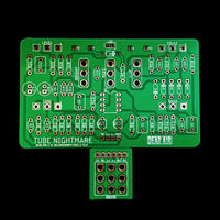
Included is the Tube Nightmare PCB and the 3PDT (footswitch) PCB.
The idea for the Tube Nightmare came about as I was looking at various existing Tube Screamer diy PCBs that were available and trying to decide which one to make. There were several mods that were of interest, but the existing builds could only accommodate one or two at the same time. I then decided to embrace the fears of option paralysis and summoned the Tube Nightmare.
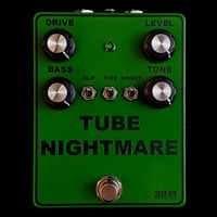
There are a few options that one could alter on this build which I'll detail below. If built with the stock parts list in the Bill of Materials this is a Tube Screamer with the following mods:
- Wider Gain Rage - From clean to high gain.
- Bass Knob - Increases low end into the circuit pre-gain and as a result increases gain as well.
- Clip Switch - 3 clipping options (symmetrical silicon, asymmetrical silicon, and no diodes)
- Mids Switch - Decreases the signature mid hump. Depending on other settings this can be fairly subtle. This also decreases gain a bit.
- Bright Switch - The stock setting rolls off a lot of high end. This allows you to bring some back with two brighter options.
The traditional Gain, Tone, and Volume knobs are there as well.
For stock Screamer tones, all switches should be up and the bass knob should be all the way down.
OTHER OPTIONS, IF YOU WANT THEM:
- BRIGHT SWITCH -
I've included room for an additional capacitor to allow the brightness to be potentially fine tuned when switched to the down position. C10 can be omitted, or socketed for experimentation. See additional notes in the Bill of Materials. To be honest, I initially thought I might prefer it less bright, but now think I prefer C10 omitted. Find out for yourself if you're curious.
- CLIPPING -
I kept the clipping pretty straight forward, but feel free to socket the diodes and experiment. Diodes D5 and D6 are the stock silicon pair, so it might make more sense to experiment with D2, D3, and D4. One possible version that could be cool would be to use LEDs in D2 and D3 and then jump D4 with wire.
BUILD INFO:
** Please note that it is assumed that anyone buying and building this is familiar with building pedals, has the necessary tools, understands parts orientation, wiring, etc, etc. I've included some info in the Bill of Materials notes, but it is far from a comprehensive list of instructions. I will try to answer questions if they come up, but I cannot offer comprehensive support.
I didn't want to offer full kits, but I also know that parts sourcing can be daunting if you're not accustomed to it. For this reason in the Bill of Materials I have included color coded links for every part needed by placing orders with Love My Switches and Tayda. Most of the parts I recommend getting from Love My Switches you may be able to find less expensively from other brands and sources, but from my experience these are items where you definitely get what you pay for and it's worth buying better quality for less headaches and a sturdier build.
ENCLOSURES:
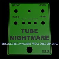
The awesome folks at OBSCURA MFG are offering enclosures that are professionally drilled, powder coated, and printed. They look amazing, and will save you time and potential headaches. Not to mention you’ll end up with a fully professional looking build.
Purchase The Obscura MFG Enclosure Here
The Obscura enclosure has the LED hole drilled out to the specs of the Tayda bezel in the Bill of Materials. If you are ordering the Obscura enclosure and will not be ordering parts from Tayda, I can provide a bezel at no additional charge. To receive this bezel, please use the note field when checking out and write something along the lines of "INCLUDE BEZEL FOR OBSCURA ENCLOSURE."
** If you don't pick up an Obscura enclosure, don't forget to get a 1590BB in your order from Tayda or Love My Switches, etc.
DOCUMENTS:
[ Drill Guide - Print Without Scaling ]
[ Component Organizer - To Print ]
(I strongly suggest organizing everything you need before you start building, this will help you make sure nothing is missing or out of place and reduces your chance of error. You can print the pdf and sort and tape all of your needed parts. This is mainly for the Resistors, Capacitors, and Diodes - the other parts are just included so it’s a complete list. )
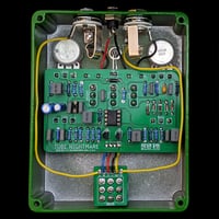
[ You'll end up with something like this ]


